Aleph Reed Relay Application Notes
Handling
Shock forces (e.g., drop from a height of 30cm or more) or application of high pull or twist forces to external terminals may result in permanent damage to relays.Cleaning
For selection of cleaners to be used on transfer molded reed relays, see the table.* Note: ultrasonic cleaning may cause permanent damage to the relay contacts
| Freon | Freon | Recommended |
| Alpha | ||
| Alcohol | Ethanol | Recommended |
| Isopropyl alcohol | ||
| Chloride | Chlorosen | Acceptable/Contitionally Acceptable |
| Chlorosolder | ||
| Trichloroethylene | ||
| Water-based compound | Indusco | Acceptable |
| Hollis | ||
| Thinner | Thinner | Not Recommended |
| Gasoline |
Mounting relays on printed circuit boards
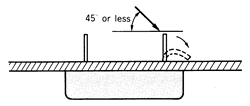 Bending
of Terminals:
If it is necessary to bend relay terminals after insertion into
a printed circuit board (pcb), the bending angle (between the
pcb and the terminal) should not be larger than 45 degrees.
An angle larger than 45 degrees may produce a vertical force
capable of causing damage to the relay mounted on the pcb.
Bending
of Terminals:
If it is necessary to bend relay terminals after insertion into
a printed circuit board (pcb), the bending angle (between the
pcb and the terminal) should not be larger than 45 degrees.
An angle larger than 45 degrees may produce a vertical force
capable of causing damage to the relay mounted on the pcb.- Soldering:
The following flux and solvent (cleaner) are recommended for
use on reed relays:
- Flux: non-corrosive, rosin based flux
- Solvent: chemically low active alcohol
- Placement of reed relays:
Relays are often a source of noise in electrical circuits (e.g.,
in circuits using semiconductor devices), and therefore certain
precautions are recommended:
- Provide as much spacing as is feasible between reed relays and semiconductor devices.
- Place coil suppression circuit (components) as close to the relay coil as possible.
- Avoid laying out noise sensitive (e.g., audio circuits) traces (conductors) in close proximity to relay coil circuits.
- As a general rule of pcb design, the shortest possible traces (conductors) should be chosen.
- Shields or shielding pcb patterns may, in some situations, be required to separate sensitive electronic circuits from power supplies and relays
Contact protection
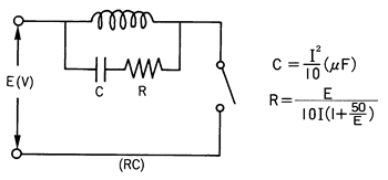
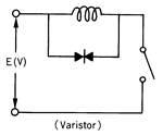
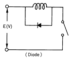
- Inductive Loads: When using relays for inductive loads such as motors, relay coils, solenoids, etc., the contacts will be subjected to high induced voltages during opening of the contacts (load circuit). Such high induced voltages (transients) may cause damage to the reed relay’s contacts and significantly reduce its life. Therefore, protective circuits such as: RC (snubber), varistors or clamping diodes, are recommended.
 |
|
 |
 |
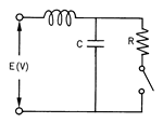
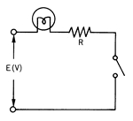
- Capacitive Loads: When using reed relays for capacitive loads such as capacitors, incandescent lamps or long cables (harnesses), the reed relay contacts will be subjected to high surge (inrush) current. Therefore, protective circuits such as: surge suppressors or current limiting resistors, are recommended.
 |
 |
Magnetic interference
 The
presence of strong magnetic fields caused by transformers, magnets,
iron plates, etc., in close proximity to the reed relay, may
cause a change of its characteristics and result in erroneous
operation.
The
presence of strong magnetic fields caused by transformers, magnets,
iron plates, etc., in close proximity to the reed relay, may
cause a change of its characteristics and result in erroneous
operation.- Placing two or more reed relays in close proximity to one another may cause magnetic interference between them, resulting in a change of operational characteristics and a possible erroneous operation. To eliminate such interference between adjacent relays, they should be spaced a minimum of 15mm from one another.
Note: Even when a reed relay equipped with a magnetic shield is selected (as means of reducing magnetic interference), it is still recommended that the 15mm minimum distance is used between adjacent relays.
Capacitive interference
Stray capacitances, such as between reed switch contacts and between the contacts and the relay’s coil, may cause signal coupling and cross-talk, especially at high frequencies and with low level signals. By selecting a reed relay equipped with electrostatic shield, such stray capacitances and the resulting signal coupling and cross-talk are greatly reduced.