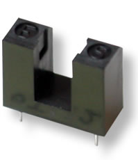
Aleph OJ-121 Opto Sensor
- Sensing Slot Width: 5 mm
Maximum Ratings (Ta=25 °C)
| Item | Symbol | Value | |
|---|---|---|---|
| Light Emitting Side | Forward Current | IF | 40mA |
| Reverse Voltage | VR | 3V | |
| Power Dissipation | PD | 75mW | |
| Light Receiving Side | C-E Voltage | VCEO | 30V |
| E-C Voltage | VECO | 5V | |
| Collector Current | IC | 20mA | |
| Collector Power Dissipation | PC | 100mW | |
| Operating Temperature 1 | TOPR | -25~+85 °C | |
| Storage Temperature | TSTG | -40~+85 °C | |
| Soldering Temperature | TSOL | 260 °C | |
1: Non Dew
Electrical Characteristics (Ta=25 °C)
| Item | Symbol | Conditions | Min | Typ | Max | Unit | ||
|---|---|---|---|---|---|---|---|---|
| Light Emitting Side | Forward Current | VF | IF=20mA | – | – | 1.5 | V | |
| Reverse Voltage | IR | IF=5V | – | – | 10 | mA | ||
| Peak Wavelength | lP | IF=20mA | 940 | nm | ||||
| Light Receiving Side | Off-State Collector Current | ICEO | VCE=10V
IF=0mA |
– | – | 0.2 | mA | |
| Peak Wavelength | lP | – | 800 | nm | ||||
| Transmitting | On-State Collector Current | IC (on) | VCE=5V
IF=20mA |
0.5 | 2.0 | 15 | mA | |
| C-E Saturation Voltage | VC (sat) | IF=20mA
IC=400mA |
– | – | 0.4 | V | ||
| Switching Time | Rise Time | tr | VCC=10V 2
IF=20mA RL=1kW |
– | 15 | – | ms | |
| Fall Time | tf | – | 15 | – | ms | |||
Note 2:
Mechanical Characteristics
| Vibration Resistance | To withstand 10~55~10Hz, 1.5mm amplitude and 1 minute sweep time in X, Y and Z directions, each for 2 hours. |
| Shock Resistance | 294m/S2 (30G) or more. |
Connection Diagram
| Terminal No. | Signal |
|---|---|
| 1 | Anode |
| 2 | Cathode |
| 3 | Collector |
| 4 | Emitter |
Detecting Position Characteristics (Reference) (IF=20mA, VCE=5V, Ta=25°C)
 |
 |
 |
|
Outline Dimensions
Tolerance: ±0.3mm
Notes- 1. Please do not submit weighting not less than 0.5kgf per a terminal.
- 2. Please be careful about a curve of a PBC.
Installation Hole Dimensions (Reference)
 Part Side Measurement
Tolerance: ±0.1mm
Part Side Measurement
Tolerance: ±0.1mm
Parts Construction List
| No. | Description | Qty. | Materials | Remarks |
|---|---|---|---|---|
| 1 | Case | 1 | PBT (G15%) | Flammability: UL94V-2 or more |
| 2 | Cover | 1 | PBT (G15%) | Flammability: UL94V-2 or more |
| 3 | Light Emitting Diode | 1 | – | GaAs Infrared Light Emitting Diode |
| 4 | Emitter | 1 | – | Photo Transistor |
Handling Notes
- Careful attention should be made to avoid deformation of components.
- Environmental air must be free from corrosive gasses such as hydrogen sulfide or salt water air.
- Mount sensor away from direct sunlight and incandescent light.
- The side with emitting and receiving elements should be handled very carefully.
- Do not wash sensors. Liquid may get into the case and cause damage. If you must clean the surface area, use a soft cloth damped with a washing fluid such as methanol or isopropyl alcohol.
- Degrading LED radiant power should be addressed if sensor is used repeatedly over a long period of time.
- This product was designed for use in the following applications:
- OA equipment, video equipment, consumer electronics, communication equipment, measuring equipment, and control equipment.
- When designing a system for safety and reliability, be sure to incorporate fail-safe and other appropriate measures.